Phase 1 Desk Test Wiring
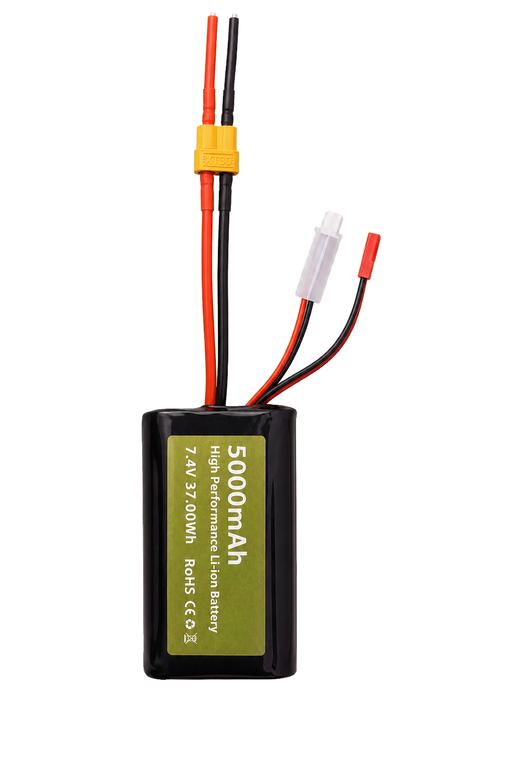
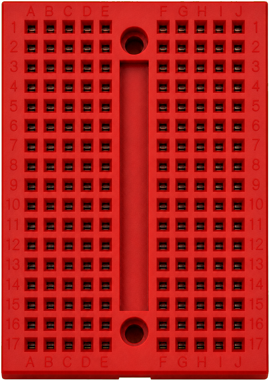
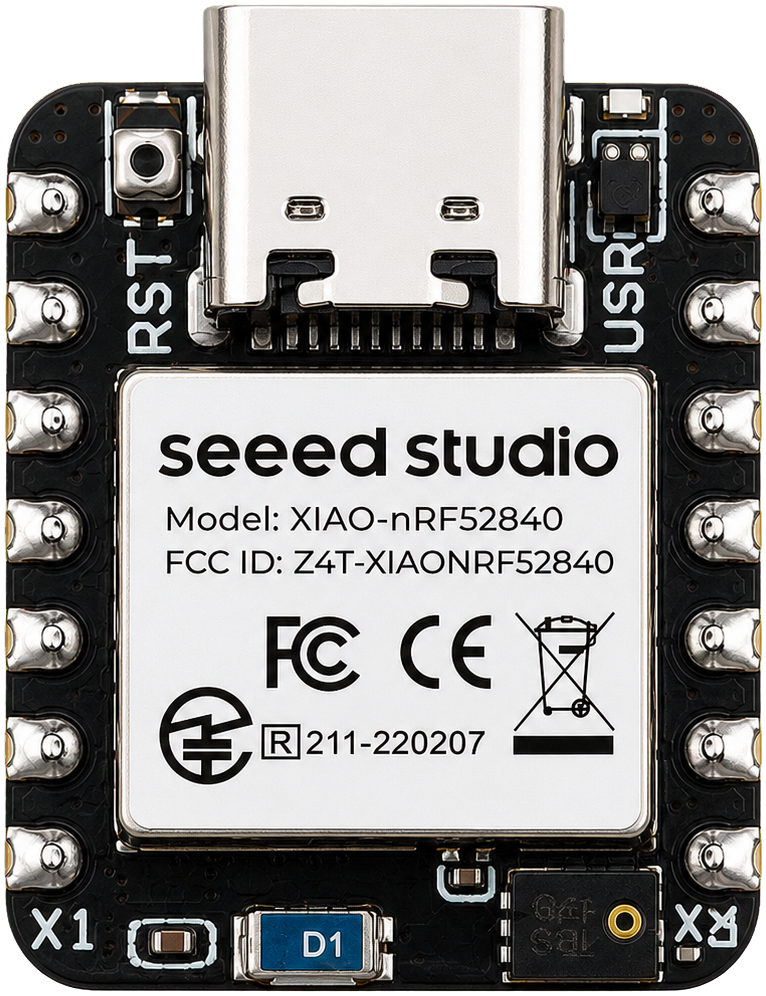
No-solder bench layout for the door unlocker prototype. The servo gets direct battery power; the XIAO only handles logic power and the PWM control signal through the breadboard.
Clean bench wiring map
Unframed parts follow the planned enclosure stack; separate side callouts identify each component and connection.
Component bodies use one approximately consistent 4-5 px/mm scale from the measured CAD envelopes; flexible wire lengths are diagrammatic.
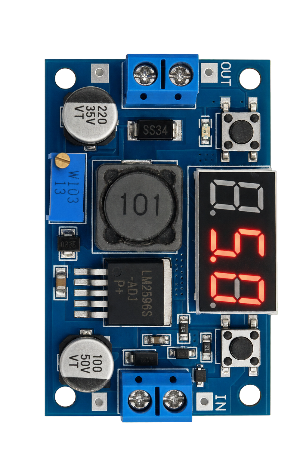
Buck mode: battery powers the servo and the XIAO through the buck after the output is set to 5.0V.
Do not plug USB-C into the XIAO while buck 5V is connected to 5V/VBUS.
Positive power
Ground
5V logic
PWM signal
USB-C from computer
!
PWM through the breadboard is fine. Do not route servo red/brown power through the breadboard.
Optimal Component Direction
This is the power-optimized parts direction for the cleaner enclosure and later product versions. The current parts are still right for desk testing; this list shows what we should migrate toward when reducing standby drain, thickness, wiring bulk, and service friction.
Low-power core
Controller and regulator
Keep the XIAO nRF52840 for the current prototype, then migrate the same BLE controller approach onto a smaller custom board when enclosure size and battery life matter more.
1Current controller. Keep using the Seeed XIAO nRF52840 Sense through Phase 1/2 while the firmware, pairing, and app flows are still moving quickly.
22S direct low-IQ buck. Replace the LM2596 with a TPS62177-class regulator for the controller rail. It fits the current 2S battery voltage range better than the 60nA TPS62840, which is not a direct 2S input part.
3Accessory rail only if needed. A TPS62933-class 3A buck is a better later choice if cameras, sensors, or a higher-current accessory rail become real.
Servo power
Physical cutoff
The servo should be electrically disconnected when locked. That is the big idle-power win beyond software detach.
1Prototype cutoff. Use the MOSFET switch module already added to the cart for bench testing, but verify with a multimeter whether it switches positive or ground.
2Cleaner prototype switch. A Pololu Big MOSFET Slide Switch MP is documented as a high-side switch and fits 4.5V-40V systems.
3Product switch. Move toward a real high-side/smart high-side stage using TI or Infineon parts after stall current is measured.
Battery and solar
Protected charging path
Solar should be treated as a charging subsystem, not a wire that goes straight into the battery.
1Panels. The current cheap 6V panels are fine for experiments. For a cleaner enclosure, test waterproof ETFE/monocrystalline panels such as Voltaic 1.2W 6V or the Adafruit 6V 1W panel.
22S solar charger. Use a BQ24650-class solar charger with MPPT, configured for the exact 2S lithium pack and panel stack.
3Protection and balancing. Keep using protected packs; if we build a custom pack later, include a 2S protection/balancing path such as the TI bq2920x family.
Telemetry and service
Battery visibility and swap
The first version should stay simple, then add better telemetry once a custom board is justified.
1Battery percentage now. Use a switched high-value divider into the XIAO ADC so it only draws power while measuring.
2Battery gauge later. Move to a MAX17263-class multi-cell fuel gauge when we need accurate SOC, time-to-empty, current, age, and telemetry.
3Quick swap. Keep the fixed XT30 dock for Phase 1.5/2. Only move to spring contacts or pogo contacts if the parts are rated with enough current and wear margin.
Later hardening
Water, heat, and safety
This is not needed for the desk prototype, but it belongs in the optimal path before any product-style build.
WWater resistance. Add gasketed seams, coated PCBs, drainage/venting decisions, and ingress testing rather than assuming the print itself is waterproof.
TThermal safety. PLA is not the final direct-sun material. Use material testing, temperature sensing near power electronics, and charger/servo fault limits before treating it as product-ready.
FFire protection. Add fusing/current limits, protected charging, battery spacing, and eventually flame-retardant material review.
Next Build Phases
Phase 1 proves the wiring and software on the desk. Phase 1.5 adds a practical three-part removable mount, then the next phases move toward a cleaner enclosure, a more universal unlocker that supports different door hardware, and eventually a cheaper product-ready design.
Phase 1.5
Three-part removable mount
Before the full enclosure, build a simple 3D printed mounting system with three printed parts: a Command-strip back plate that stays on the door, a removable electronics/servo sled that slides onto it, and a near full-height service cover for maintenance. The battery should slide out quickly for charging, while the controller, wiring, inline splitters, and servo stay firmly mounted.
1Door mounting plate. Fixed 2in x 264mm adhesive spine with four Command strip pairs, hidden behind the enclosure for a cleaner installed look.
2Main enclosure sled. Controller, buck, inline splitters, wiring, battery pocket, and servo mount stay secured to the removable module.
3Service cover. Near full-height removable cover, ideally on shallow dovetail rails, so maintenance does not require peeling the door plate off.
RDovetail rails. Open-ended rails keep the sled tight against the plate, with a hidden detent or thumb release to stop accidental release.
EAdjustment slots. Servo bracket and arm position should use a notched removable cradle so the servo can shift height without losing tight side support.
QQuick-swap battery. Use a fixed XT30 dock in the housing, a chamfered slide-up battery slot, a small pull ribbon/lip, and a thumb latch so charging does not disturb the internal wiring.
WFixed harness routing. Mold ten open snap-in grooves into the enclosure behind the service cover. Keep servo positive on the outer left, servo ground on the outer right, battery feeds just inside them, and the five 22 AWG controller paths through the center. One spare 16 AWG groove is reserved for the future high-side servo switch.
Phase 2
Integrated printed housing
After the Phase 1.5 slide-on mount works, the next enclosure should merge the sled into a cleaner, mostly vertical housing. The goal is to stay thin off the door instead of stacking thickness: solar/status LED at the top, servo and arm near the handle, controller plus inline-splitter service bay below that, and the removable battery at the bottom. That vertical layout should also make servicing easier because parts are not buried behind each other depth-wise.
1Thin vertical stack. Lay parts out by height instead of depth: solar/status LED, then servo/arm, then controller plus inline-splitter service bay, then bottom battery. Nothing should be stacked depth-wise in a way that blocks service access.
2Slide-up battery bay. Battery should sit low, slide up from the bottom, mate into a fixed XT30 dock, click into a small latch, and pull out quickly for charging or replacement.
3Solar panel mount. Housing should reserve a thin front/service-cover solar skin for two 110 x 60 mm, 6V/1W mini panels wired in series, with the final panel split relieved around the servo pocket and routed to a real 2S lithium solar charger.
4Servo power cutoff. Add a controller-driven load switch so the servo is physically unpowered when locked, but powered while moving or holding the handle down in unlocked mode.
5Back-plate compatibility. Keep the same slide-on mount pattern so the full enclosure can reuse the Phase 1.5 door plate.
6Serviceable wiring. Prefer connectors, sockets, inline lever splitters, or small screw terminals so battery, servo, controller, switch, and charger can be replaced. Keep the harness in dedicated snap-in grooves on the main sled so removing the cover or a component does not erase the wiring layout.
7Shielding-ready layout. Leave room for foil, grounded shielding, ferrites, or cable routing changes around the controller and servo leads if EMI/RFI testing shows noise issues.
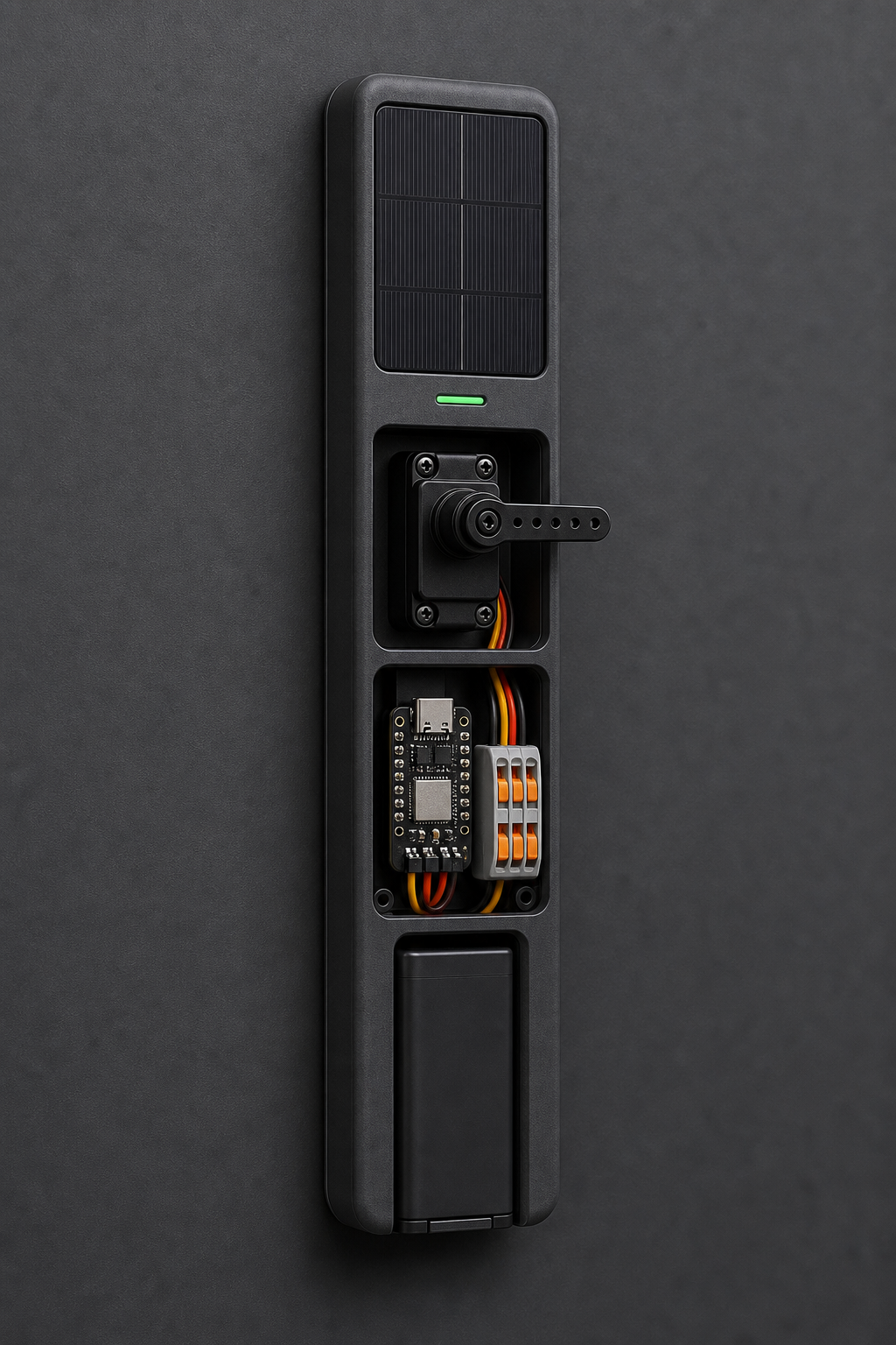
AI-generated concept image. The real Phase 2 enclosure will likely be much sleeker and thinner; this is only a visual direction for the housing, battery slot, solar area, and service layout.
Phase 3
Handle-attached mount
After the simple Command strip mount works, the next mechanical upgrade is a bracket that attaches around the fixed part of the handle assembly. That should make the unit easier to move between doors and reduce reliance on adhesive strength.
AAround-handle bracket. Clamp around the fixed rose/escutcheon area when the door hardware shape allows it.
BDoor-agnostic geometry. Keep the servo position adjustable so future handle styles can be supported.
CSolder only where it helps. Permanent solder joints can improve reliability, but modular connectors may be better for upgrades and field repair.
Phase 4
Universal door support
This phase turns the project from a lever pusher into a more flexible unlocker. The bracket should still attach around a fixed part of the handle assembly, but the actuator side should support more than one unlock motion. A small vision system can help the unit understand handle/lock geometry, guide placement, and eventually make better inside/outside presence decisions for auto-unlock.
AMultiple actuator modes. Push a lever down, rotate a thumbturn/turnpiece, press a privacy button, or drive a future handle-mounted module.
BMore universal geometry. Adjustable arms, offsets, and contact tips should fit more door hardware without custom parts for every door.
CDual-camera vision setup. Explore one forward-facing camera for handle/turnpiece/button geometry and one inward-facing room-side camera for inside approach context, so future versions can tell whether auto-unlock should happen when someone is actually near the door from inside.
DLower-cost BOM pass. Keep the prototype flexible, but start replacing expensive one-off parts with cheaper equivalents where reliability is not hurt.
Phase 5
Sellable product version
Phase 5 is where the design moves from a project to something that could be sold. The focus shifts toward repeatable assembly, cheaper custom parts, reliability testing, tamper-resistant interior hardware, water-resistant construction, battery/fire safety, interference shielding, and a clean install experience.
ACustom low-cost parts. Replace bulky prototype hardware with purpose-built brackets, actuator tips, and enclosure pieces.
BProduction electronics. Move toward a cleaner board, smaller wiring harness, high-side servo power switching, ultra-low-power battery monitoring, protected solar charging, and fewer hand-assembled connections.
CReady-to-install package. Include the mount, battery, charging path, setup flow, safety limits, and clear compatibility guidance.
DInterior tamper resistance. Cover wiring, add strain relief, hide casual-access fasteners, and enclose moving parts while keeping owner service access possible.
EWater and thermal safety. Add splash/humidity protection, drainage or sealing where needed, flame-retardant material choices, fusing, protected battery charging, and basic thermal fault handling.
FInterference shielding validation. Add EMI/RFI shielding, cleaner cable routing, filtered power paths, and real-world shielding validation so wireless control, sensors, and future accessories stay reliable in noisy apartments.
GVision setup hardening. If the Phase 4 dual-camera setup works, refine privacy controls, lens placement, lighting tolerance, offline calibration, and failure recovery so vision helps installation and presence context without becoming a constant recording feature.
HAccess roles. Add owner/admin versus standard trusted-device permissions so some phones can approve new devices or change critical settings while others only lock and unlock.
Phase 6+
Cost, quality, design, and R&D
Later phases are about owning more of the system, lowering cost, increasing quality, and polishing the parts that matter most: industrial design, thinness, power use, mechanical reliability, app experience, manufacturing, advanced batteries, high-efficiency solar, removable door swing add-ons, integrated door concepts, and future access-control integrations.
AOwn the core modules. Custom actuator, power, battery, charging, and enclosure systems can reduce cost, improve quality, and make the product thinner.
BReliability lab work. Measure cycle life, battery drain, solar recovery, water ingress, thermal faults, stall behavior, adhesive/bracket load, and door-to-door compatibility.
CFuture integrations. Explore deeper platform support such as Matter, HomeKit-style control, UWB-assisted presence, and richer diagnostics.
DIndustrial design polish. Refine the look, reduce thickness, hide bulk, improve material finish, and make the mounted unit feel sleeker and more intentional.
EDoor swing add-on. Design and build our own easily removable companion add-on that pairs with the unlocker to automatically open and close common doors using an innovative, quick-install mechanism such as controlled magnetic assist, with force limits, obstacle detection, and manual override.
FIntegrated door platform. Explore a future installable door system with the unlocker and swing motion built in, using innovative hardware such as magnetic-hinge concepts to reduce noise, creaks, and visible bulk.
GAdvanced power stack. Evaluate solid-state battery options, higher-efficiency solar cells, better charge management, and energy-harvesting layouts once the product design is mature enough to justify custom power hardware.
HExterior doorbell face-recognition add-on. Explore a separate weather-resistant outside module with a doorbell button, camera, face recognition, privacy controls, and secure handoff to the interior unlocker.
IRated enclosure research. Work toward real IP-rated sealing, thermal protection, ingress testing, and fault detection after the removable interior design is proven.
Door Mounting Plate 3D Concept
The fixed door piece is the door mounting plate. The enclosure is the removable electronics housing that slides onto this plate. This cleaner concept uses a flush 2 inch x 264 mm adhesive spine hidden behind the enclosure, with open-ended rails and a small internal detent instead of visible load stops.
The interactive 3D model could not load. The fit notes below still document the measured plate, rail, enclosure, adhesive, and component envelopes.
Dimension-driven fit model · millimeters
Component inspector
Full assembly
Door mounting plate
Flush fixed backplate sized to hide behind the 264 mm enclosure, so the mount mostly disappears once the sled is installed.
2 in W x 264 mm H, 7 mm thickFlush fixed backplate sized to hide behind the 264 mm enclosure, so the mount mostly disappears once the sled is installed.
Dual captive dovetail rails
Raised male rails are formula-driven trapezoids: 8 mm neck, 14.35 mm head, 5.5 mm depth, and 0.40 mm per-side channel clearance. Rails are open-ended for easier slide-on removal.
30 mm spacing, 244 mm solid railRaised male rails are formula-driven trapezoids: 8 mm neck, 14.35 mm head, 5.5 mm depth, and 0.40 mm per-side channel clearance. Rails are open-ended for easier slide-on removal.
Printed parts
Print one flush hidden door mounting plate, one main enclosure sled, and one near full-height sliding service cover.
3 totalPrint one flush hidden door mounting plate, one main enclosure sled, and one near full-height sliding service cover.
Depth-separated servo plane
The servo body stays inside the deeper front chamber while only its output pivot and arm pass through the narrow full-height slot.
30 x 24 x 238 mm arm slotThe servo body stays inside the deeper front chamber while only its output pivot and arm pass through the narrow full-height slot.
Continuous servo height track
A 52 x 46 x 3.2mm clamped carriage slides on two 220mm rails in an independent front plane, allowing the servo to align with the handle without rearranging the rear electronics.
22–242 mm center rangeA 52 x 46 x 3.2mm clamped carriage slides on two 220mm rails in an independent front plane, allowing the servo to align with the handle without rearranging the rear electronics.
Hidden retention
No bulky top or bottom stop. A low-profile click detent keeps the sled from creeping, but intentional removal stays a straight slide.
small internal detentNo bulky top or bottom stop. A low-profile click detent keeps the sled from creeping, but intentional removal stays a straight slide.
Adhesive backing
Use two columns by two rows. The fit is tight on the flush plate: about 1.2 mm side margin, 8.9 mm top/bottom margin, and 4.0 mm between rows.
4 x 17217 XL pairs, 111.1 x 22.2 x 1.6 mmUse two columns by two rows. The fit is tight on the flush plate: about 1.2 mm side margin, 8.9 mm top/bottom margin, and 4.0 mm between rows.
Force check
Four pairs are not enough for a 3x full-stall target. They are acceptable only if measured handle force stays around 4.9 lbf or lower for a 3x margin.
4 pairs = 1.28x vs servo stallFour pairs are not enough for a 3x full-stall target. They are acceptable only if measured handle force stays around 4.9 lbf or lower for a 3x margin.
Validation test
Command ratings are static picture-hanging ratings, so the real door needs a staged load and cycle test before the plate is trusted on the door.
measure handle force firstCommand ratings are static picture-hanging ratings, so the real door needs a staged load and cycle test before the plate is trusted on the door.
Bambu PLA Pure print
Print the flush plate flat, print dovetail coupons first, and keep heat/creep testing in mind before trusting it on a hot door.
P1S, 0.4 mm nozzle, 0.40 mm rail clearancePrint the flush plate flat, print dovetail coupons first, and keep heat/creep testing in mind before trusting it on a hot door.
Dimension confidence
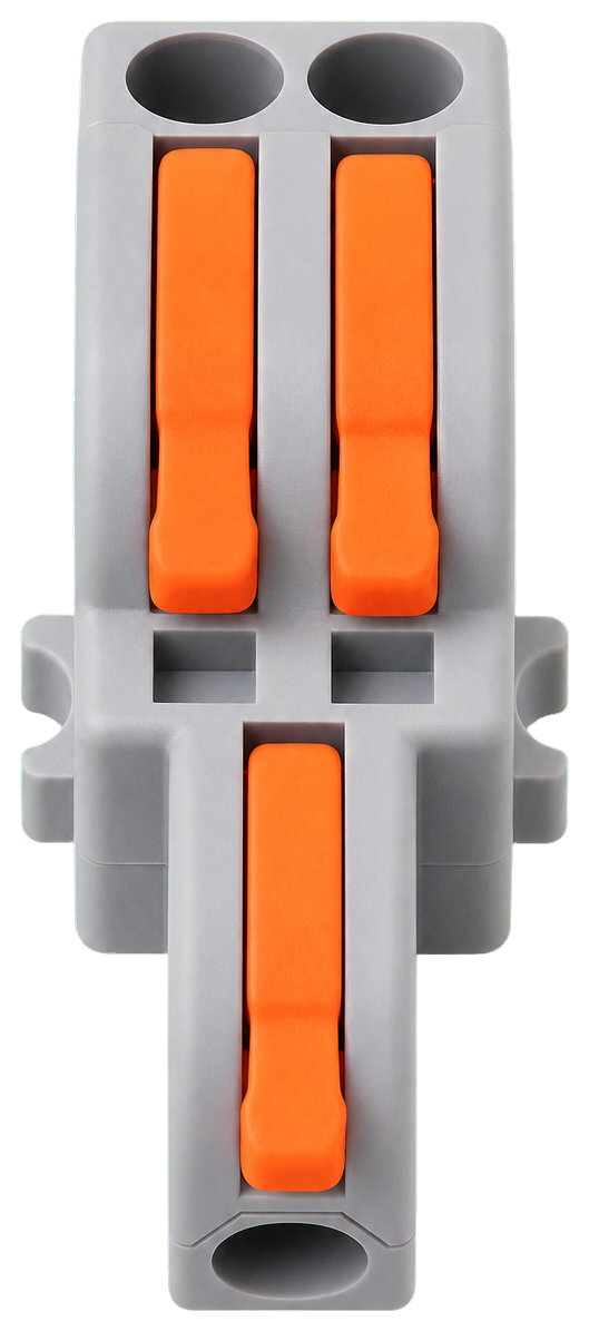
Vendor-confirmed dimensions drive the plate, servo, XIAO footprint, inline splitters, buck, and solar panels. The splitter dimensions come from the purchased listing graphic; verify the actual parts with calipers before printing.
verified + estimated geometryVendor-confirmed dimensions drive the plate, servo, XIAO footprint, inline splitters, buck, and solar panels. The splitter dimensions come from the purchased listing graphic; verify the actual parts with calipers before printing.
Clean-map harness routing
The 3D cutaway follows the clean bench order: battery, upright joined inline splitters, vertical buck, centered breadboard/XIAO, then servo. The 16 AWG servo feeds rise symmetrically on the outer edges, battery feeds stay just inside them, and five 22 AWG controller paths use the center. Nine grooves are active; one 16 AWG groove is reserved for the future high-side switch. Raised 1 mm ribs preserve the full 3.2 mm rear wall.
10 grooves, z 78-222 mmThe 3D cutaway follows the clean bench order: battery, upright joined inline splitters, vertical buck, centered breadboard/XIAO, then servo. The 16 AWG servo feeds rise symmetrically on the outer edges, battery feeds stay just inside them, and five 22 AWG controller paths use the center. Nine grooves are active; one 16 AWG groove is reserved for the future high-side switch. Raised 1 mm ribs preserve the full 3.2 mm rear wall.
Phase boundary
This Phase 1.5 viewer intentionally excludes an external status LED, solar panels, charger, and servo power-switch board. Those remain Phase 2 fit work and are documented separately below.
current hardware onlyThis Phase 1.5 viewer intentionally excludes an external status LED, solar panels, charger, and servo power-switch board. Those remain Phase 2 fit work and are documented separately below.
Phase 2 CAD Fit Model
This is the first Bambu P1S-oriented print pass: a parametric two-plane enclosure plus a color-coded fit preview. The design is three printed parts: a flush 264 mm mounting plate, a 264 mm enclosure sled with built-in wire-routing troughs, and a 252 mm removable service cover. The plate and sled print flat and diagonally on the 256 x 256 mm P1S bed. The 56mm depth preserves the clean rear electronics stack while giving the servo its own continuously adjustable front plane.
Three printed parts
Print one 50.8 x 7 x 264mm hidden mounting plate, one 72 x 56 x 264mm enclosure sled, and one 66 x 2.2 x 252mm service cover. Rotate the two long parts diagonally on the P1S bed.
plate + sled + coverPrint one 50.8 x 7 x 264mm hidden mounting plate, one 72 x 56 x 264mm enclosure sled, and one 66 x 2.2 x 252mm service cover. Rotate the two long parts diagonally on the P1S bed.
Fit simulation
The 72 x 56 x 264mm housing has 96.5% vertical utilization, 66.8% width utilization, 46.0% rear-component depth utilization, 10.9mm minimum side clearance, 3.8mm inter-plane clearance, and zero modeled component collisions.
264 mm tight minimumThe 72 x 56 x 264mm housing has 96.5% vertical utilization, 66.8% width utilization, 46.0% rear-component depth utilization, 10.9mm minimum side clearance, 3.8mm inter-plane clearance, and zero modeled component collisions.
Plate height check
Removing visible top/bottom stops lets the plate match the enclosure height. Open-ended rails keep the mount clean, and a hidden detent handles retention.
264 mm flush hidden plateRemoving visible top/bottom stops lets the plate match the enclosure height. Open-ended rails keep the mount clean, and a hidden detent handles retention.
Solar skin
Use two thin 6V/1W panels in series for a 12V-class charger input. The rectangular envelope fits the face, but the servo pocket interrupts it, so the final split must clear the servo and still allow service access.
2 x 110 x 60 mm panelsUse two thin 6V/1W panels in series for a 12V-class charger input. The rectangular envelope fits the face, but the servo pocket interrupts it, so the final split must clear the servo and still allow service access.
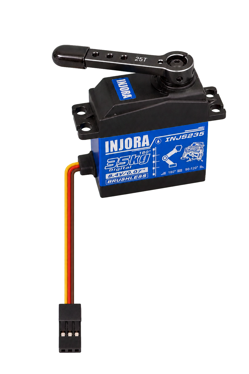
Independent servo plane
Holds the 40.5 x 20 x 37.5mm INJORA servo on a clamped carriage. Its center can move continuously from 22 to 242mm while a 30 x 24 x 238mm front slot exposes the pivot and arm.
dual 220 mm rails + narrow front slotHolds the 40.5 x 20 x 37.5mm INJORA servo on a clamped carriage. Its center can move continuously from 22 to 242mm while a 30 x 24 x 238mm front slot exposes the pivot and arm.
XIAO controller
Vendor footprint with separate board thickness, header pins, and USB-C connector shown in the detailed cutaway.
21 W x 17.8 H boardVendor footprint with separate board thickness, header pins, and USB-C connector shown in the detailed cutaway.
No-solder breadboard
Standard 170-point board shown vertically in the cutaway, with the XIAO and headers modeled separately on its front face.
35 W x 8.5 D x 47 HStandard 170-point board shown vertically in the cutaway, with the XIAO and headers modeled separately on its front face.
Inline splitter pair
The purchased 1-in/2-out connectors are physically joined side-by-side at one height while remaining electrically separate, matching the clean bench map.
2 x 32 W x 13.5 D x 13 HThe purchased 1-in/2-out connectors are physically joined side-by-side at one height while remaining electrically separate, matching the clean bench map.
Current buck module
Purchased Seloky B0DM946DHG envelope, rotated vertically. This can shrink later with the low-quiescent regulator plan.
40 W x 10 D x 60 HPurchased Seloky B0DM946DHG envelope, rotated vertically. This can shrink later with the low-quiescent regulator plan.
Battery cartridge
Bottom-inserting pack in a 46.5 x 25 x 80.5mm slot, mostly inside the enclosure with only a small pull lip exposed.
43 W x 22 D x 75 HBottom-inserting pack in a 46.5 x 25 x 80.5mm slot, mostly inside the enclosure with only a small pull lip exposed.
Battery quick swap
The controller-side XT30 should be fixed to the housing with slight connector float. The battery slides up into chamfered guides, mates automatically, and releases with a thumb latch or spring tab.
fixed XT30 dock + pull lipThe controller-side XT30 should be fixed to the housing with slight connector float. The battery slides up into chamfered guides, mates automatically, and releases with a thumb latch or spring tab.
Servo power switch
Prototype MOSFET module cuts servo supply power when locked. Final wiring should switch the high side, keep common ground shared, and prevent PWM back-powering when the switch is off.
42 x 26 mm board footprintPrototype MOSFET module cuts servo supply power when locked. Final wiring should switch the high side, keep common ground shared, and prevent PWM back-powering when the switch is off.
Estimated mass
Components including the no-solder breadboard are about 390g, printed PLA parts about 390g, and the full door-supported assembly about 794g. Force math still rounds this up to 1.8lb.
638 g enclosure, 794 g installedComponents including the no-solder breadboard are about 390g, printed PLA parts about 390g, and the full door-supported assembly about 794g. Force math still rounds this up to 1.8lb.
PLA force check
Bambu PLA Pure checks pass the first-order printed-part load, and the open-ended rails keep 10 mm end margins. The four Command pairs still do not meet a 3x full-stall adhesive target.
6.65 MPa plate bend, 0.0172 MPa rail shearBambu PLA Pure checks pass the first-order printed-part load, and the open-ended rails keep 10 mm end margins. The four Command pairs still do not meet a 3x full-stall adhesive target.